Introduction
Autosar (Automotive Open Source Architecture) is a methodology of architecture based on global partnership of automotive companies focused on practices and process to magnify benefits on the ECU development area. Autosar architecture permits the handling and management of complexity of E/E architectures to increase re usability and interchange of ECUs architectures among OEMs or suppliers.
Autosar promotes architecture standardizations that yields to improvement of performance, safety, security, and environmental care for complex automotive systems. In the SW perspective, Autosar allows to:
- Decouple Software (SW) and Hardware(HW) by the abstraction of HW drivers and services management inside different layers of basic SW modules.
- Decouple of SW entities with different common functionalities by horizontal grouping.
- Reuse of SW that improves quality and efficiency.
An example of decouple SW is that a system without Autosar standardized architecture is highly dependent of the HW specifications, so re-usability is mostly impossible. Moreover, the SW development might be inefficient because requires low-level HW support. When “migrating” to an Autosar architecture system, SW is decoupled of the HW detailed specs and it is further divided into basic SW and application SW. This permits a high rate of re-usability that yields a high degree of efficient SW development.

Autosar Features
Autosar principal features are:
- Architecture: SW architecture with configurable basic SW, a middle-ware called RTE (Run-Time Environment) to handle the communication between the BSW and application.
- Methodology: ECU description formats and templates to configure processes of basic SW and application SW integration.
- Application interface: Standardized interface collection to communicate application in order to use them on a wide variety of automotive domains.
- Acceptance Tests: acceptance test to validate the behavior of Autosar requirements.
Principal challenges of Autosar are solutions to support complex software infrastructures, highly automatized complex systems, Car2X applications, hard real-time systems, high-velocity transmission, and systems with frequent interaction from sensors, actuators, and other ECUs. To support these highly demanding systems types, all Autosar implementation shall relies on 4 pillars to form the standard solution for the automotive ECU development.
- Functional Safety: mature safety features such as robust watchdog, safe E2E communication, and so on.
- Efficiency: Flexibility based on the use of Complex Device Drivers and cost-effectiveness by supporting different microcontrollers.
- Mature application: Established development process and improved quality due to widespread implementations.
- Performance: Hard real-time capabilities, event trigger support, and scalability by configurations.
Autosar Classic vs Adaptive Autosar
Autosar architecture has two variations, Autosar Classic and Adaptive Autosar. Autosar Classic is focused on effective solutions while Adaptive Autosar is focused on flexible solutions.
Adaptive Autosar is out of scope for this introduction.
Autosar Software Architecture
The following diagram is a simplified example of a system with AUTOSAR which involves two entities. SWC and VBF.
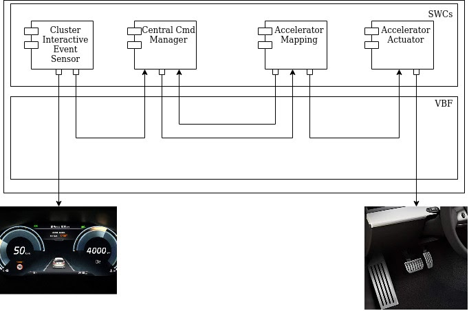
Autosar Software Component (SWC) is any application encapsulation of functionalities on top of the basic SW layer, SWCs interface to BSW to fulfill requirements and define its Software Component description (SWCD). SWCs have communication to the upper layer of BSW services modules through ports and interfaces. So SWCs are intended to define custom behaviors that can be decoupled by BSW and be easier to reuse.
Besides the intra-ECU communication, the application might require communication with other ECUs so inter-ECU communication is available by the use of vehicle network protocols supported by Autosar (CAN, LIN, FlexGate, and Ethernet). At the SWC level, this does not reflect much changes due to the signal abstraction and because all communication is also managed by BSW.
Software Components
SWC can contain multiple port clusters. These clusters can group interrelated interfaces. For example, there are 2 types of ports used in Autosar SWCs:
- Sender/Receiver are interface ports that support n: 1 or 1: n communication. This communication type is based on the transmission of data elements. These data elements are sent by the sender and requested by the receiver through application runnable. The Sender / Receiver interface ports calls are synchronous and are performed in the same context as the sender. In this context, communication boundaries are ports that are configured based on runnable of the involved SWC.
- Client / Server are interface ports that support n: 1 communication only, the call to a server is implemented from runnable of the server-SWC and can be synchronous or asynchronous. Client/Server ports can use the same client context (unmapped server) or within another context (mapped server). Multiple clients can request/invoke services/functions from the server.
VFB
The Virtual Functional Bus (VBF) is the high level definition of the system level software components that are connected between them. Therefore, these functional components can be associated with system resources of the ECU or other functional components. These associations can be local or ECUs level (using CAN, LIN, FR, Ethernet). In this case, RTE works as an interface to serve all these software components and be able to be connected to the BSW, using local and ECU level associations. Based on VFB, all the components contains an specific factor of the functionality and they would be independent of the communication with relative software components, so in this way, the VBF is the definition of any consistency between software components to be able to be correct and be able to be saved on the system description, which defines the inputs and outputs of each software component in different levels ( systems, ECU connection, ECU internal connection).
Software Components
A software component is the principal part of the system on VFB definition level. Each component defines ports that are unique to that component and those port permit the component to communicate with other components globally or within ECU. A software component can be used multiple times in a system (reusability).
Software components communicate through ports. All port is associated with a port interface that permits the contract to be able to communicate through that port. In Autosar, there is the principal ports
- Provided Port (P-Port), defines Sender/Receiver (S/R) that provides a transmission signal and defines Client /Service (C/S) to forward a service to a client.
- Require Port (R-Port), defines Sender/Receiver (S/R) to reception of signals, and defines Clients /Service (C/S) to reception of services of a server.
The interface type of Sender/Receiver connect the information based on data forms for one or more receptor by one or more transmissions. The mode management can be used to determine which receptor and transmissions to use. This type of interfaces can be supported by the following port types:
- RPort The component consume a data value.

- PPort The component delivers a data value

- PRPort The component can consume and delivers the data values of specific port.
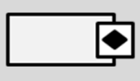
- Autosar RPort The component consumes a data value of Autosar specification service.

- Autosar PPort The component delivers a data value of Autosar specification service.

- Autosar PRPor t The component can consume or deliver a service based on the Autosar specification service

The interface type of Client / Service is the transmission of a transmission operation to multiples receptors, so those receptors can use the operation. This type of interface can be supported by the next port types
- RPort Client This components uses the operation defined in the interface. If black, means Autosar specification operation.

- PPort Server This component implements the operation defined. If black, means Autosar-specification operation.

- PRort Client Server This component uses and implements operations defined in the interface.

The interface type of interface of parameter allows access to constant data such as compilation constant, calibration, or fixed data. No connection of a defined variable is not possible so the interfaces shall be congruent and be connected to its supported pair. This type of interface can be supported by the next port types.
- RPort Parameter This component obtains the parameter data. If black, means Autosar-specification parameter.

- PPort Parameter This component transmits the parameter data. If black means Autosar-specific parameter.

The interface type Trigger allows the callback of a software component from other software component to permit fast responses to sporadic events. This type of interface can be supported by the next port types.
- RPort Trigger This component contains a trigger sink. If black, means Autosar-specification trigger

- PPort Trigger This component contains a source of triggers. If black, means Autosar-spec trigger

- PRPort Trigger This component contains a source and a sink of triggers. If black, means Autosar-spec trigger
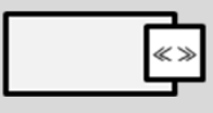
The interface type Mode Switch allows software components to be notified by a mode. This type of interface can be supported by these port types.
- RPort Switch This component has a switch mode user. If blacks, means Autosar specification mode switch user.
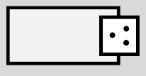
- PPort Switch This component has a manager of switch mode. If black, means Autosar specification manager of switch mode.
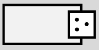
- PRPort Switch This component has a manager and user of switch mode. If black, means Autosar specification manager of switch mode.

The interface type NV data interface allows the access to NVM blocks to read and write. This type of interface can be supported by these port types
- RPort NV This component requires access to a NV block data. If black, means Autosar specification NV access request.

- PPort NV This component allow access to a NV block data. If black, means Autosar specification NV access enabled.

- PRPort NV This component allows and requires access to a NV block data. If black, means Autosar specification NV access enabled and request.

Reference
- Autosar specification 4.3
- Virtual Bus Function Autosar specification 4.3

